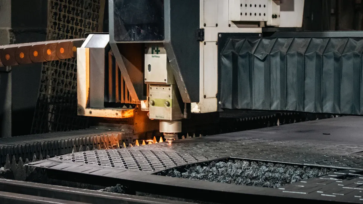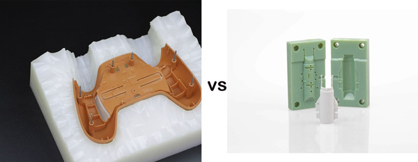
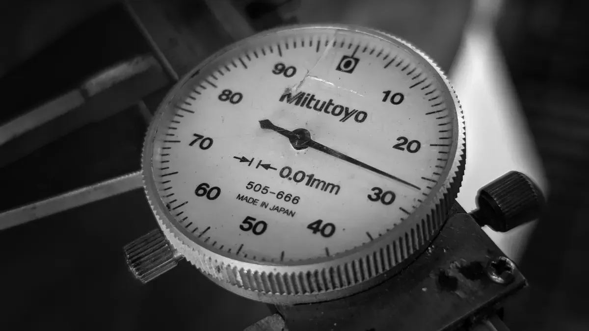
Standard tolerances are general allowances for non-critical features, usually ±0.005 in (±0.1 mm). Critical dimensions are the few features that need tighter control, often ±0.001 in, because they govern fit, function, safety, or assembly.
Variation always occurs in CNC machining tolerances. Tolerances define the acceptable range; they do not eliminate variation. That distinction shapes every drawing decision.
This guide is for product designers, mechanical engineers, and buyers who source prototypes and low-volume parts. It explains what each type of CNC machining tolerance means, when each one applies, and how the choice affects cost and performance. Readers can then set realistic limits on a drawing and discuss them with a machining partner before release.
Key Takeaways
Use standard tolerances for most features to save money and time.
Save critical tolerances for features that affect fit, function, or safety.
Tighter tolerances make machining cost more and add to inspection work.
Check the total of all the tolerances to prevent problems when putting parts together.
Check tolerances with your machining partner before you finalize the design.
Standard CNC Machining Tolerances
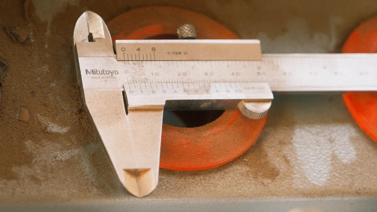
Standard tolerances are the usual general allowances on a drawing. They cover features that do not control fit, function, safety, or assembly. A common value is ±0.005 in (±0.1 mm) for machined metal parts. This number is a common industry example, not a universal rule. The value depends on the process, the material, and the shop’s own defaults.
Typical Values and ISO 2768
ISO 2768 defines general tolerance classes for linear and angular dimensions. The standard publishes four classes: f (fine), m (medium), c (coarse), and v (very coarse). Each class sets a tolerance band that gets wider as the nominal dimension grows.
Class | Name | Relative band |
|---|---|---|
f | Fine | Tightest of the four |
m | Medium | Common default for machined parts |
c | Coarse | Wider band |
v | Very coarse | Widest band |
These values are references, not guarantees. Supplier defaults vary, and a shop may use its own general block tolerance. Always confirm the default before release. A drawing that cites ISO 2768 without a class leaves the band open to interpretation.
Best Uses for Standard Tolerances
Standard tolerances work well for non-critical features, decorative surfaces, consumer goods, and cost-sensitive projects. They keep machining time and inspection effort low. A bracket hole that only clears a cable, or a cosmetic edge on an enclosure, rarely needs tighter control.
Material also changes the default. General guidance puts metals near ±0.005 in and plastics near ±0.01 in, because plastics move more under cutting stress and temperature. Treat these numbers as starting points. They are not universal standards, and they do not replace a shop’s confirmed capability. Use standard CNC machining tolerances wherever function allows, and save tight limits for the features that truly need them.
Critical Dimensions
What Makes a Dimension Critical
A critical dimension is a feature that controls fit, function, safety, or assembly. These features decide whether a part works, not just whether it looks right. A shaft journal that holds a bearing, a mounting hole pattern that lines up with a mating frame, or a sealing groove that holds a gasket all count. If the feature fails, the whole assembly fails with it.
Critical dimensions have tighter limits than the general block. Precision work often lands near ±0.001 in. Very tight aerospace and medical work can reach ±0.0005 in. These values are common industry examples, not a shop capability. They also come with conditions: small part size, stable material, and a controlled process.
The decision table below splits the two categories by the criteria that matter most during quoting and inspection.
Criterion | Standard dimensions | Critical dimensions |
|---|---|---|
Typical tolerance | ±0.005 in (±0.1 mm) for metals | ±0.001 in, down to ±0.0005 in for very tight work |
Feature type | Non-critical, cosmetic, clearance | Fit, function, safety, assembly |
Cost impact | Low; default toolpaths and sampling | Higher; slower cutting, extra operations, more inspection |
Inspection need | Spot checks with calipers | Documented checks with micrometers, gauges, or CMM |
Typical applications | Enclosures, brackets, covers | Bearing seats, mating bores, sealing faces |
Tight Values and Industry Examples
Aerospace parts often pair large structures with a few tight interfaces. A wing fitting bore may need ±0.0005 in so a bushing seats without play. Medical devices show the same pattern. A surgical instrument pivot or an implant mating surface needs tight control, because a loose fit affects function and patient safety.
Automotive work relies on critical dimensions at bearings and mating features. A transmission bearing seat that runs tight keeps vibration low and service life long. A cylinder head mating face that runs flat seals combustion gas. Each example is illustrative. The right value still depends on the design intent, the material, and the process.
Designers should mark these features clearly on the drawing and leave the rest at standard limits. That habit keeps CNC machining tolerances realistic and keeps cost focused where function demands it.
Tolerance Types and Standards
Bilateral, Unilateral, Limit, and GD&T
A drawing can show a tolerance in more than one way. Each method fits a different feature, and each one changes how a machinist reads the print.
Type | Example | How to read it |
|---|---|---|
Bilateral | 30 +0.05/-0.05 mm | The size can be 0.05 mm above or below 30 mm |
Unilateral | 70 +0.00/-0.05 mm | The size can only be smaller than 70 mm |
Limit | 12…12.5 mm | Any size between the two limits passes |
GD&T | Form, orientation, location, runout | Controls geometry, not just size |
Bilateral tolerances split the allowance evenly around the nominal size. Unilateral tolerances push the allowance to one side, which fits a shaft that must never be bigger than its nominal diameter. Limit dimensions state the acceptable range directly and leave no math for the operator.
GD&T does more. It controls form, orientation, location, and runout through feature control frames. ASME Y14.5, ISO 1101, and BS 8888:2020 define these symbols. GD&T ties a feature to datums, so it describes function rather than size alone.
ISO 2768, ASME Y14.5, and Limits and Fits
ISO 286-2 governs limits and fits. A hole basis H7 paired with a shaft basis g6 makes a common clearance fit for locating parts. Tolerance grades 6 through 9 cover most machined work. Grade 6 needs fine control and often extra operations. Grade 9 is looser and cheaper to hold. The grade choice directly shapes machining time and inspection effort.
References sometimes conflict. A supplier table may quote a tighter default than the drawing standard. The rule is simple: defer to primary standards such as ISO 2768 and ASME Y14.5, and to material datasheets. Never treat any supplier’s tolerance table as a universal standard. Confirm the governing reference before release, and state it on the drawing so every party reads the same CNC machining tolerances.
Cost and Performance
Why Tight Tolerances Cost More
A tight limit changes the whole machining plan. The shop must slow the feed rate and the spindle speed to hold a smaller band. Slower cutting adds time to every pass. Some features then need a second operation, such as grinding or lapping, to reach the final size. Each extra step adds setup time and handling.
Special fixtures raise the cost further. A thin wall or a small bore may need a custom support block to resist deflection during the cut. Frequent tool changes add more minutes, because a worn tool drifts out of the band sooner. Inspection also grows. A ±0.001 in feature needs documented checks with micrometers or a CMM, not a quick caliper spot check. Scrap risk rises at the same time. One small drift can push a part outside a narrow band, and the whole part becomes waste.
These drivers compound. A single tight bore may add minutes, but a drawing full of tight limits can double the cycle. Buyers should expect a higher quote for that work, and the increase is usually justified by the extra effort.
Performance Trade-Offs
Tighter CNC machining tolerances improve fit and assembly reliability. A bearing seats without play. A mating pair joins without force. A seal holds pressure. These gains matter most in moving assemblies and safety-related joints.
The trade-off appears in sourcing and schedule. Fewer shops can hold very tight bands, so the buyer has fewer options and less leverage on lead time. A shop may also queue the job behind simpler work. Looser limits open the supplier pool and shorten delivery, but they raise the risk of assembly problems. A clearance hole that runs large may still bolt up, yet it can shift position and stress the joint.
Neither choice is wrong. A cosmetic cover fits loose limits well. A spindle housing does not. The right answer depends on what the feature does, not on a habit of tightening everything.
General guidance stops here. Koonze-specific cost data, capability limits, and lead times for tight work require [KOONZE INPUT NEEDED]. Confirm those figures with the shop before quoting a project.
Selecting CNC Machining Tolerances
A good tolerance plan starts before the drawing leaves the design desk. The goal is simple: put tight limits only where function demands them, and let everything else run at the general block. The workflow below turns that goal into a repeatable habit.
A Step-by-Step Workflow
Find the critical features first. List every surface that controls fit, function, safety, or assembly. A bearing seat, a mating bore, and a sealing face belong on this list. A cosmetic edge does not.
Give standard tolerances to everything else. Let the general block cover clearance holes, covers, and surfaces that do not mate. A typical metal default is near ±0.005 in (±0.1 mm). This is an industry example, not a shop guarantee.
Use GD&T only where it helps. Put feature control frames on features that need orientation or location control. Skip them on simple clearance holes, where a size tolerance already does the job.
Check process capability before release. Make sure the shop can hold each tight band on the chosen material and part size. A limit the process cannot repeat becomes scrap, not quality.
Avoid over-tolerancing. Every extra tight callout adds cutting time, inspection, and cost. Look over the drawing once more and loosen any limit that does not protect function.
Note: Dimensions you do not specify fall back to the supplier’s default block. State that default on the drawing so every party reads the same CNC machining tolerances.
Material, Process, and Part Size
Material properties shape what a process can hold. Hard and abrasive alloys wear tools faster, so the cut drifts sooner and the band narrows. Heat-stable materials hold size well during cutting. Materials with high thermal expansion move more when the temperature changes, and that movement works against a tight limit. A part measured warm can pass, then fail once it cools to room temperature.
Part size matters just as much. A long dimension makes every small error bigger, and a large frame flexes under cutting force. Large parts and high-expansion materials therefore make tight tolerances harder to hold. Small, stiff parts on stable material give the best chance of success.
Drawing callouts carry the plan to the shop. Place each tolerance next to the dimension it controls, and reference datums that match how the part functions. Features that relate to each other should be machined in one setup, because a second setup adds a new alignment error between them. Confirm shop-specific capability limits with [KOONZE INPUT NEEDED] before committing a tight band to production.
Inspecting Critical Dimensions

Tools and the 20 °C Reference
The tool you pick should match the feature you are checking. A caliper gives a fast reading on an outside dimension. A micrometer gives a finer reading on shafts and thicknesses. Pin and plug gauges check hole size against a go/no-go limit. Bore gauges measure inside diameters, and height gauges check features from a surface plate. A coordinate measuring machine (CMM) captures location and geometry across many features in one setup. Surface roughness testers confirm finish where a sealing face or bearing seat needs it.
Temperature changes every reading at the micron level. The accepted reference is 20 °C (68 °F), the temperature where a part and a gauge share the same size. Aluminum expands by roughly 23 µm per meter for each 1 °C rise. So a 300 mm aluminum part measured 5 °C above reference reads about 35 µm larger than its true size at 20 °C. That shift alone can exceed a ±0.001 in band. Micron-level work needs a controlled room and a CMM, not a caliper on a warm bench.
Documentation and Reports
Inspection records prove that a part met its drawing. A first article inspection report documents every dimension on the first part of a run. A CMM report lists measured values against nominal and tolerance for each critical feature. Material certificates trace the alloy and heat lot back to the mill. A full inspection report covers the whole batch with sampling or 100 percent checks.
Buyers should request the report type that matches the risk. A prototype with one tight bore needs a first article report. A safety-related batch may need full inspection. Koonze-specific inspection report samples and sampling plans require [KOONZE INPUT NEEDED]. Confirm the report format before release, so the records arrive in a form the quality team can review.
Common Pitfalls
Tolerance Stack-Up
Parts can pass their own inspection and still fail when put together. Imagine two plates, each with a hole, connected by two pins. Each hole is within its limit, and each pin is within its limit. But the small errors still add up across the pair. One plate pushes its holes left, the other pushes right, and the pins no longer line up. The assembly gets stuck even though no single part broke its drawing.
Stack-up analysis finds this problem before release. A worst-case study adds every tolerance in the chain at its extreme. It shows the largest possible gap or interference. A statistical study treats each tolerance as a distribution and estimates how often the assembly fails. Designers should run one of these checks on any chain of three or more mating parts. GD&T with functional datums helps too. It ties each feature to the surface that actually locates the part, so the tolerance reflects real assembly behavior instead of an arbitrary edge.
Over-Constraining and Adjustment Features
Over-constraining means two things. It can mean an unnecessarily tight tolerance on a feature that does not need one. It can also mean holding a degree of freedom more than once, such as pinning a plate at four holes when two would locate it. Both mistakes raise cost. The first adds cutting time and inspection. The second fights the assembly, because the part cannot move to settle into place.
Adjustment features offer a practical alternative to overly tight CNC machining tolerances. Shims fill a gap after assembly. Adjustment screws let a user set position on site. Press fitting and shrink fitting create a controlled interference that holds parts without a tight size band on every surface. Each method absorbs variation instead of fighting it.
Bench fitting and fettling suit prototyping well. A technician can file or lap a part to fit on the bench. That approach does not scale to high-volume production, where every manual step adds time and inconsistency. Designers should plan for adjustment features early and save hand work for one-off builds.
Save critical dimensions for the few features that really need tight control. Let standard tolerances cover everything else. This balance keeps a drawing honest and keeps cost focused where function demands it. A careful plan for CNC machining tolerances protects both performance and budget.
Tighter limits raise machining time, inspection effort, and scrap risk. Designers should therefore check each design against material, part size, process capability, and assembly needs. Confirm every tolerance choice with the machining partner before release. A clear, well-reviewed drawing gives every party the same target, and that shared target is the surest path to parts that fit the first time.
FAQ
Does every drawing need critical dimensions?
No. A drawing only needs critical dimensions on features that control fit, function, safety, or assembly. Most features can use the general block, like ±0.005 in (±0.1 mm) for metals. That value is a typical industry example, not a shop guarantee. Fewer tight callouts mean lower cost and less inspection.
Which standard governs when a drawing and a supplier table disagree?
The primary standard wins. Follow ISO 2768 for general tolerances and ASME Y14.5 for GD&T, then check the material datasheet. A supplier’s tolerance table is a shop reference, not a universal rule. State the governing standard and its class on the drawing so every party reads the same limits.
Can a shop hold ±0.001 in on any part?
Not always. Very tight bands depend on part size, material stability, and process control. Large parts and high-expansion materials make the band harder to hold. Small, stiff parts on stable material give the best chance. Confirm the shop’s capability before release; Koonze-specific limits require [KOONZE INPUT NEEDED].
Why does a part pass inspection but fail to assemble?
Tolerance stack-up explains it. Each part can sit inside its own limit, yet the small errors add up across a chain of mating features. Two plates with offset holes can still miss their pins. Run a worst-case or statistical study on chains of three or more parts, and tie GD&T to functional datums.