The fastest way to lower CNC cost and lead time is to design holes, threads, internal corners, deep cavities, and thin walls around standard tooling and standard sizes before the part is quoted.
This checklist is for product designers, mechanical engineers, and buyers who source CNC prototypes and low-volume parts. Use it as a set of CNC machining design tips you can apply at the CAD stage, when changes cost almost nothing.
Each item follows one pattern: the problem, how it affects cost or function, and a fix you can make. Units and conditions appear wherever a number matters. Deeper topics get their own separate articles.
Key Takeaways
-
Make holes 2.5 mm or bigger, and keep the depth within six times the diameter.
-
Specify threads that are M6 or larger, and keep the thread depth within three times the diameter.
-
Make the inside corner curves about 30% bigger than the cutter’s diameter.
-
Keep the cavity depth no more than four times the cavity width.
-
Keep the wall height at no more than three times the wall thickness.
CNC Machining Design Tips: Holes, Threads and Corners
Holes, threads and internal corners dominate machining cost because each one forces a tool into a shape the cutter cannot reach freely, and that single constraint sets the tool size, the number of setups and the cycle time for the whole part.
Why These Features Drive Cost
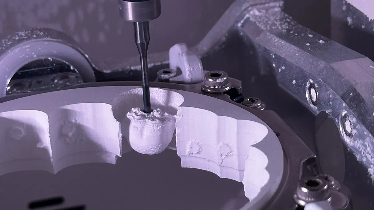
A cutter removes material along a path. A hole needs a plunge, a thread needs a synchronized motion, and a corner needs a radius the tool can physically fit into. Each of these motions adds time, and time is the largest cost driver in CNC work.
These features also interact. A deep hole may demand a longer, thinner tool. A sharp internal corner may demand a smaller cutter that must run slower. Change one feature and the cost of its neighbors can move too.
Note: Treat every number in this checklist as typical industry practice under stated conditions. Your shop’s tooling, machine and material will shift the real limits.
How to Read This Checklist
Each item follows the same pattern. You get the problem, the effect on cost or function, and a fix you can apply in CAD. Apply the fix before you request a quote, when edits are still free.
Use these CNC machining design tips as a screening pass, not a rulebook. Some parts genuinely need a deep pocket or a fine thread. In those cases, document the reason so your supplier can plan the process around it.
The sections that follow cover holes, threads and corners in turn. Later sections fold in walls, tolerances and workholding. Each deep topic has its own dedicated article.
Holes: Size, Depth and Access

Hole design sets the drill or end mill your supplier reaches for first. That choice ripples through tool changes, peck cycles and inspection time. Apply these CNC machining design tips early and the savings compound across every hole pattern on the part.
Standard Sizes and the 2.5 mm Floor
Problem: You specify a 1.8 mm hole for a fastener clearance or a vent. The cutter must be small, fragile and slow.
Effect: Small tools break more often, run at reduced feed rates and need more frequent replacement. Each break risks a scrapped part and a restarted setup. Cost climbs even though the hole removes almost no material.
Fix: Keep hole diameters at 2.5 mm (about 0.098 in) or larger, and snap them to standard drill and end mill sizes. Standard sizes mean the tool is already on the shelf. A slightly larger hole often costs less than a smaller one.
Tip: Check every hole against the nearest standard size before you finalize the drawing. A 0.1 mm change can move a hole from custom tooling to stock tooling.
Depth Limits and Blind Holes
Problem: You call out a deep, narrow hole. Depth grows faster than diameter, and chip evacuation gets harder with every pass.
Effect: Deep holes need peck drilling, extra coolant and longer cycle times. Tool deflection rises, so the hole drifts off position and the finish suffers. A blind hole adds a flat-bottom or drill-point decision on top.
Fix: Hold hole depth to about six times the diameter as typical industry practice. Beyond that ratio, expect a longer tool, a slower program and a higher quote. Specify the drill point angle or a flat bottom explicitly, and give a usable depth rather than a full-depth callout.
|
Hole condition |
Typical practice |
What it means for you |
|---|---|---|
|
Diameter |
2.5 mm (0.098 in) or larger |
Stock tooling, lower cost |
|
Depth-to-diameter ratio |
Up to about 6:1 |
Standard drilling, predictable cycle |
|
Beyond 6:1 |
Longer, thinner tool |
Slower program, higher risk |
|
Blind hole |
State point angle and usable depth |
Avoids ambiguity at quote |
For Koonze’s specific minimum hole diameter and maximum depth-to-diameter ratio, insert [KOONZE INPUT NEEDED].
Threads: Sizes and Depth Limits
Threads add a synchronized motion to the cut, and that motion is where cost hides. Apply these CNC machining design tips to thread callouts and you avoid the small taps that break and the deep threads that stall a program.
Why M6 and Larger Saves Money
Problem: You call out an M3 or M4 thread in a metal part. The tap is thin, and the hole beneath it is small.
Effect: Small taps snap under torque, especially in hard alloys. A broken tap can scrap the part or demand careful removal. Deep small threads also need slower spindle speeds and more operator attention.
Fix: Specify M6 (about 0.236 in) or larger as a typical industry minimum for machined threads in metal. Larger threads tolerate more torque and run at higher speeds. If a small thread is functionally required, say so on the drawing so your supplier can plan for it.
Thread depth follows the same logic as hole depth. Keep thread depth within about three times the nominal diameter as typical practice. A deeper thread adds tapping time and raises the risk of tap breakage, and it rarely adds holding strength.
Note: These are general guidelines under typical conditions. Material, thread class and tooling change the real limits.
Thread Milling vs. Tapping
Tapping drives a shaped tool into the hole and cuts the thread in one pass. It suits standard sizes, moderate depths and higher volumes, where the cycle time per hole matters most.
Thread milling cuts the thread with a rotating cutter on a helical path. It suits large diameters, tough materials and parts where a broken tap would be costly to remove. It also lets one tool cut several thread sizes.
Choose tapping for simple, repeated threads. Choose thread milling for large or critical threads. Neither method is better in every case.
For Koonze’s specific thread milling and tapping capabilities, insert [KOONZE INPUT NEEDED].
Internal Corners: Radius and Depth
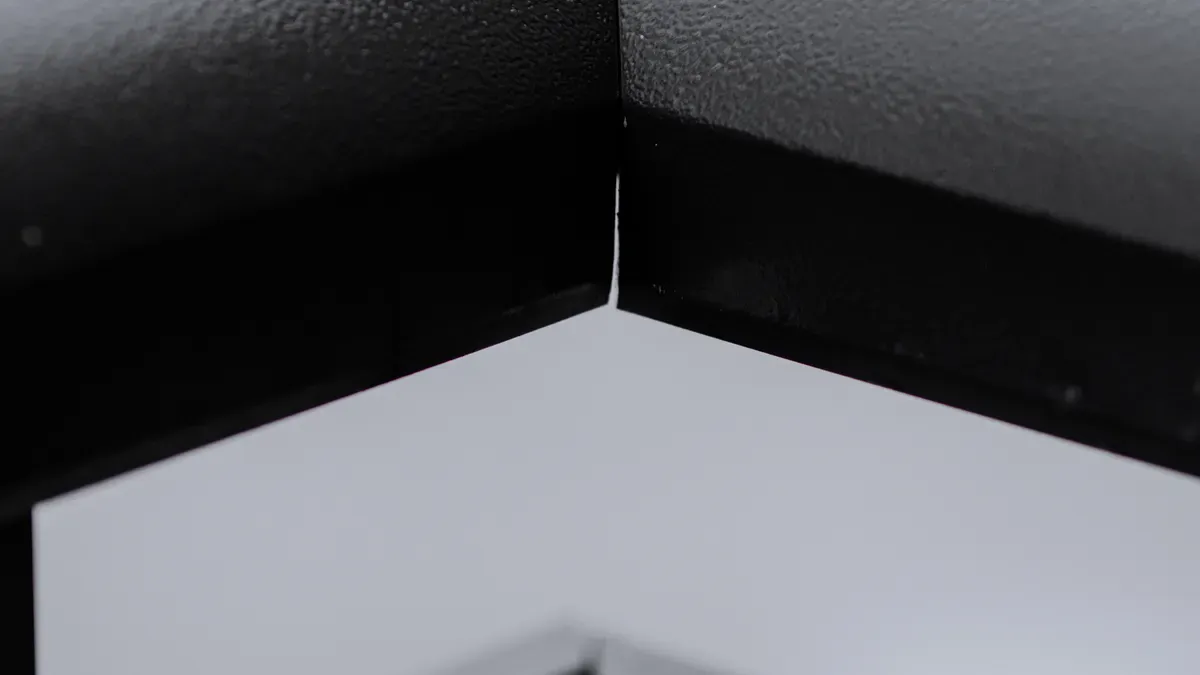
An internal corner is where a rotating cutter must change direction inside the part. The radius you draw there decides which tool can reach the floor. Get this one feature right and you remove a whole class of cost from the quote.
The 30% Corner Radius Rule
Problem: You draw a sharp 90-degree internal corner, or a radius smaller than the cutter. The tool cannot cut a square inside corner, so your supplier must either leave a larger radius or switch to a smaller cutter.
Effect: A smaller cutter runs slower, deflects more and wears faster. A sharp corner may also need a second operation, such as EDM, to clean out the material the mill cannot reach. Both paths add time and cost.
Fix: Size the corner radius at about 30% larger than the cutter diameter you expect the shop to use. As typical industry practice, a corner radius of 3 mm (about 0.118 in) or more lets a standard end mill reach the corner without a tool change. Match the radius to the pocket depth as well. A deep pocket needs a stiffer tool, and a stiffer tool means a larger radius.
Tip: Draw the corner radius on the model, not just the drawing. CAM software reads the model, and a modeled radius prevents a mismatch at the machine.
Cavity Depth-to-Width Ratios
Problem: You design a deep, narrow cavity. The cutter must reach the floor with a long, thin tool.
Effect: Long tools chatter, and chatter spoils the surface finish and the wall straightness. Your supplier must slow the program, take lighter cuts and possibly rough the cavity in stages. Cycle time rises sharply.
Fix: Hold cavity depth to about four times the cavity width as typical practice. This 4:1 ratio keeps the tool short and rigid. Use these CNC machining design tips as a quick screen before you send the model out.
|
Cavity condition |
Depth-to-width ratio |
Typical outcome |
|---|---|---|
|
Shallow |
Up to about 2:1 |
Fast, stable cutting with standard tooling |
|
Efficient |
About 3:1 to 4:1 |
Standard practice, predictable cycle time |
|
Deep |
Beyond 4:1 |
Longer tool, slower program, finish risk |
|
Maximum |
Well beyond 4:1 |
Special tooling and process planning |
Widen the cavity, split it into steps, or open one side where function allows. Each change shortens the tool and protects the finish.
Deep cavities deserve their own planning pass. A separate article covers stepped cavities, tool reach and roughing strategy in detail.
For Koonze’s specific minimum internal corner radius and maximum cavity depth-to-width ratio, insert [KOONZE INPUT NEEDED].
Cross-Cutting Rules
Some rules apply to every feature on the part, not just holes or corners. Treat these as a final check before you release the model.
CNC Machining Design Tips for Walls and Tolerances
Problem: You draw a tall, thin wall. The cutter pushes against it, and the wall bends away from the tool.
Effect: A wall that bends will chatter. Chatter ruins the surface finish and makes the wall uneven. It may also force your supplier to take lighter cuts and slow the program. In the worst case, the wall springs back and the part misses its size.
Fix: Keep wall height at about three times the wall thickness as typical practice. A 3:1 ratio keeps the wall stiff enough to machine in one pass. Make the wall thicker, add a rib, or make it shorter where function allows.
|
Wall condition |
Height-to-thickness ratio |
Typical outcome |
|---|---|---|
|
Stable |
Up to about 3:1 |
Standard tooling, clean finish |
|
Marginal |
Beyond 3:1 |
Lighter cuts, slower cycle |
|
Thin |
Well beyond 3:1 |
Chatter risk, finish and dimension loss |
Tolerances work the same way. State your default tolerance and surface roughness on the drawing. Mark tighter values only where function demands them. A tighter tolerance or a finer finish adds inspection time and extra passes. Sometimes it also adds a second setup.
Note: Tighter values need a good reason. Write down why the feature needs them, and your supplier can plan the process around that need.
Keep text and engraving simple. Shallow, wide characters cut faster than deep, narrow ones. For Koonze’s default tolerance and surface finish capabilities, insert [KOONZE INPUT NEEDED].
Setups, Workholding and Tool Access
Problem: You design a feature on a face the tool cannot reach without flipping the part.
Effect: Every additional setup adds fixturing time, a re-datum and a chance for error. Five-sided work can double the cost of a simple bracket.
Fix: Design for access from as few faces as possible. Leave room for clamps and vises, and avoid features buried behind tall walls. Apply these CNC machining design tips to the whole part, not just one feature.
Do this checklist in one pass before you ask for a quote. Keep holes at 2.5 mm or larger, and keep depth within six times the diameter. Specify threads M6 and larger, with depth within three times the diameter. Make corner radii about 30% larger than the tool, keep cavities within a 4:1 depth-to-width ratio, and keep walls within a 3:1 height-to-width ratio.
Each item makes the part easier to manufacture and lowers cost without losing function. Use this as a draft you can review for your own DFM check. Change the numbers to fit your part’s real needs, and write down any exception on the drawing.
FAQ
What is the smallest hole I should design for CNC machining?
Keep holes at 2.5 mm (about 0.098 in) or larger as typical industry practice. Smaller holes need fragile tools that break often and run slowly. Snap each diameter to a standard drill or end mill size. For Koonze’s minimum hole diameter, insert [KOONZE INPUT NEEDED].
How deep can I make a threaded hole?
Hold thread depth within about three times the nominal diameter as typical practice. Deeper threads add tapping time and raise the risk of a broken tap. They rarely add holding strength. Specify M6 (about 0.236 in) or larger where function allows. For Koonze’s thread depth limits, insert [KOONZE INPUT NEEDED].
Why can’t I draw a sharp internal corner?
A rotating cutter cannot cut a square inside corner. A sharp corner forces a smaller tool or a second operation such as EDM. Size the corner radius about 30% larger than the expected cutter. A radius of 3 mm (about 0.118 in) or more suits standard end mills.
How do I know if my cavity is too deep?
Compare cavity depth to cavity width. Keep the ratio at about 4:1 or less as typical practice. Beyond that, the tool gets long and thin, and chatter spoils the finish. Widen the cavity or open one side where function allows. For Koonze’s cavity limits, insert [KOONZE INPUT NEEDED].